List of 22 Basic Car Engine Parts & Their Functions [PDF]
Hello readers! In this post, we’ll discuss the car engine parts and their functions using pictures.
What is a Car Engine?
Contents show
The engine is a power generator, power plant, or motor that provides the energy needed to move the vehicle. The heart of your car is its engine. This device uses the heat from burning gas to rotate the wheels of a vehicle.
- The internal combustion engine is those heat engines that burn fuel inside the cylinder.
- External combustion engines are heat engines that burn their fuel outside the cylinder engine.
Now, let’s discuss the different parts of a car engine and its functions.
Parts of a Car Engine
- Cylinder Block
- Cylinder Head
- Crank Case
- Oil Pan
- Manifolds
- Gasket
- Cylinder Liner
- Piston
- A Piston Ring
- Connecting Rod
- Piston Pin
- Crank Shaft
- CamShaft
- Flywheels
- Engine Valves
- Governers
- Oil filter
- Distributor
- Water pump
- Combustion chamber
- Timing Belt
- Rocker arm
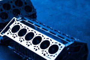
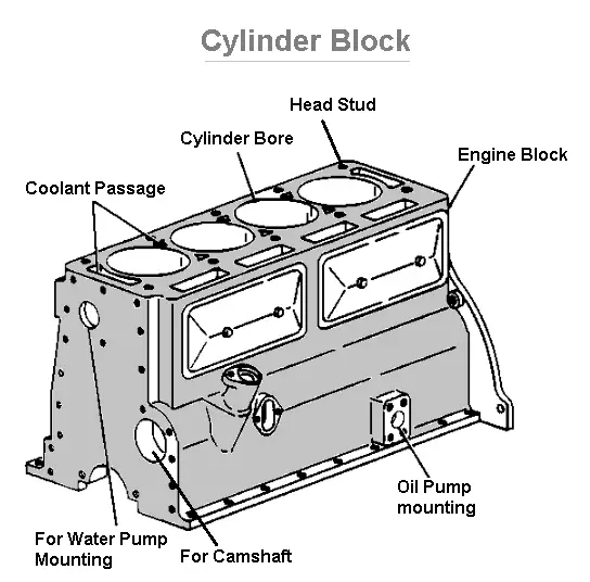
#1 Cylinder Block
Fig shows a simple sketch of the cylinder block. It is the basic framework for the engine. And one of the main engine parts. The cylinder block, cylinder head, and crankcase these three parts form the foundation and main stationary body of the automobile engine.
A cylinder block consists of three parts:
- The cylinder in which the piston slid up and down.
- The port or opening for the valves.
- The passages for the flow of cooling water.
Construction and Working:
- The cylinder block is usually made of grey cast iron or aluminum and its alloys.
- While the crankcase is fixed to its bottom, apart from these, other parts like the timing gear water pump, ignition distributor, flywheel, fuel pump, etc., are also attached to it.
- Passages are provided in the cylinder walls for the circulation of cooling water.
- The mating surfaces of the block are carefully machined to provide a perfect sealing surface.
- The cylinder block also carries lubrication oil to various components through drilled passages called oil galleries.
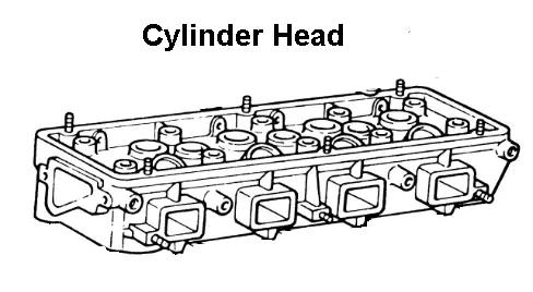
#2 Cylinder Head
Another type of engine part is cylinder head. It is a joint between the cylinder head and cylinder block.
Construction
- It is usually made up of cast iron and aluminium alloy.
- The top of the cylinder is covered by a separate cast piece know as the cylinder head.
- The cylinder head is attached to the cylinder block by means of studs fixed to the block gaskets are used to provide a tight, leak-proof joint between the head and block.
- Cylinder head contains a combustion chamber above each cylinder.
- It also contains valve guides, valve seats, ports, coolant jackets and threaded holes for spark plugs. It incorporates passages for the flow of cooling water.
Applications
- The cylinder head casts integrally with cylinder blocks also be done in a few cases usually in racing cars to obtain a gas-tight joint.
- The detachable head types are more advantages than integral construction.
- However, for certain heavy-duty engine requires high cooling rates such as in racing cars copper alloys may be used.
Types of Cylinder Head
- Loop flow type
- Offset cross flow type
- Inline cross flow type
Loop flow type: In the loop, flow types the inlet and the exhaust manifolds are on the same side, which facilitates preheating of the intake air.
Offset cross flow type: Offset cross flow types the inlet and the exhaust manifolds are placed on different sides of the cylinder head.
In line cross flow type: In-line cross-flow type, the valve is positioned transversely and usually inclined to each other, while the intake and the exhaust manifolds are on different sides of the cylinder head. This arrangement gives better performance, but it is costlier.
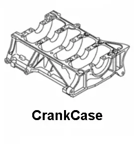
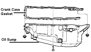
#3 Crankcase
The oil pan and the lower part of the cylinder block together are called the crankcase. It is the bottom portion of the cylinder block, in which the crankshaft is fitted.
Construction
- This is a rigid construction made of grey cast iron or aluminium. Either it can be cast integrally with the block or can be cast separately and attached to the block with bolts.
- The crankcase is shaped simply like a box having no bottom. Oil pan or sump forms the bottom half of the crankcase.
Working
- The function of the crankcase is to provide support for the main journals and bearing of the crankshaft, rigidly maintaining the alignment of their axes of rotation under various engine loads.
- The crankcase is supported in the crankcase through a number of bearing called the main bearing.
#4 Oil Pan
The bottom half of the crankcase is called the oil pan or sump. It is attached to the crankcase through set screws and with a gasket to make the joint leak proof. The oil pan serves as a reservoir for the storage, cooling and ventilation of engine lubricating oil.
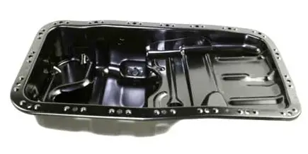
At the bottom of the oil sump, a drain plug is provided to drain out the dirty oil at the time of oil replacement. Generally, the sump is made of pressed steel sheet or aluminium alloy casting is used.
The various functions of the oil pan as follows
- To store the oil for the engine lubrication system.
- Oil pan used to collect the return oil draining
- To serve as a container for impurities or foreign matters
- Oil pan provides for cooling of the hot oil in the sump.
Working
- The oil pump in the lubricating system draws oil from the oil pan and sends it to all working parts in the engine.
- The oil drains off and runs down into the pan.
- Thus there is a constant circulation of oil between the pan and the working parts of the engine.
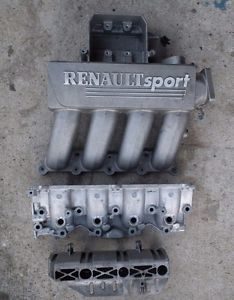
#5 Manifolds
There are separate sets of pipes attached to the cylinder head which carry the air-fuel mixture and the exhaust gases, these are called manifolds. It is generally made of cast iron so that it is able to withstand the high temperature of the exhaust gases.
Construction
- It consists of the air intake, throttle body, intake manifold flange for tail-pipe and flange for a carburettor.
Working
- The air goes into the air intake travels through, throttle body into the intake manifold and from there it goes into the engine through the cylinder head.
- The inlet manifold carries the air-fuel mixture from the carburettor to the cylinders.
- The exhaust manifold is the set of pipes carrying exhaust gases from the cylinder head to the exhaust system.
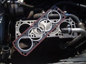
#6 Gaskets
These are used to provide a tight fitting joint between two surfaces.
Gaskets are found in
- the joint between the cylinder head and the cylinder block
- Between crankcase and oil pan.
- Between the cylinder block and manifold.
Materials used for gaskets are
Requirement/properties of the gasket as follows
- Conformity: The gaskets should conform to the mating surfaces which may have roughness or warpage.
- Resistance: It should have resistance to high pressures, extreme temperature and vibrations.
- Impermeability: The gasket must be impermeable to the fluid.
- Resistance to chemical attack: the gasket should have resistant to the chemicals such as fuel, products of combustion, coolant and engine oil.
- Provision of apertures: The gasket must have apertures for any studs, bolts, opening etc.,
Gaskets produced by the fuel-pro USA as follows
- Cylinder head gaskets.
- Oil pan gaskets.
- manifoldgaskets.
- pumpgaskets.
Types of gaskets used in engines
- Copper-asbestos gasket.
- Steel-asbestos gasket.
- Steel-asbestos-copper gasket.
- Single steel ridged or corrugated gasket.
- Stainless steel gasket.
#7 Cylinder liners
These are cylindrical shapes used in the cylinders to avoid the problem of cylinder wear. It is one of the most important functional parts to make up the interior of an engine.
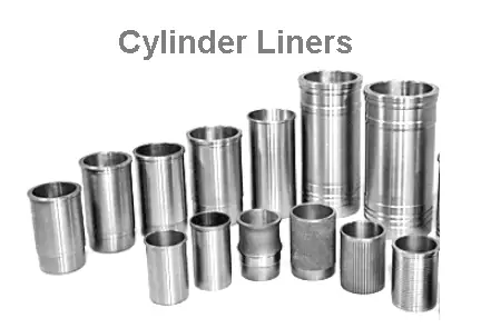
These can be replaced after they are worn out. These are made of special alloy iron containing silicon, manganese, nickel and chromium.
Usually, these are cast centrifugally. These liners resistance to wear and corrosion. These liners are of the oil hardening type and offer considerably longer life for the engine.

Cylinder Liners are of Two Types
Dry liners and wet liners. Let’s take the detail view.
Dry liners:
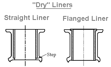
Construction: The construction of a dry liner is shown in the figure. This liner is made in the shape of a barrel with a flange at the top which keeps it into position.
The entire outer surface bears against the cylinder block casting and hence these are it be machined accurately at both outer and inner faces.
The liner should not be too loose, otherwise, the heat dissipation becomes poor because of the absence of good contact with the cylinder block.
Wet liners:
The figure shows a simple sketch of the wet liner. These liners will be in direct contact with the cooling water at their outer face.
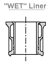
Thus, these liners need not be machined very accurately at the outer surface. However, they have been machined accurately at the inner surface. They are resisting corrosion with continuous contact with cooling water. and they coated with aluminium at their outer surface.
Construction
- At the top, the liner is provided with a flange which fits into the groove in the cylinder block.
- At the bottom of the liner is provided with a groove, generally three in number.
- The middle groove is left empty for drainage for any water that may leak from the upper ring.
- And in the top and bottom ones are inserted packing ring, made of synthetic rubber.
Comparison of the dry and wet liner
Dry Liners
- Dry liners may be provided either in the original design or even afterwards.
- The construction of the cylinder block very complicated. The cooling effect is not very good.
- Accurate machining of dry liners for perfect contact with the cylinder casting is essential.
- In this type, it cannot be finished before fitting. A leak-proof joint is not necessary.
Wet Liners
- Wet liners have to be included in the original design. The construction of the cylinder block is simple.
- The cooling effect is better because the liner will have direct contact with cooling water.
- Accurate machining is not essential. In this type, they can be finished before fitting.
- A leak-proof joint should be made between wet liner and cylinder block.
#8 Pistons
Pistons are most important engine parts compared to others. The piston is a cylindrical plug that moves up and down in the cylinder.
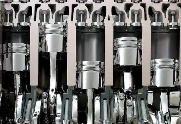
- The highest position of the piston reaches in the cylinder is called the Top Dead Centre (TDC) and
- The lowest position it reaches is called the Bottom Dead Centre (BDC).
It is provided with pistons ring about 3 to 5 provide a good seal between the cylinder wall and piston. The efficiency and economy of the engine primarily depend on the working of the piston.
- Cast iron,
- Aluminium alloy.
- Nowadays aluminium alloys are widely used. It may be either cast or forged.
The piston must possess the following qualities
- Rigidly to withstand high pressure
- Light in weight, to reduce the reciprocating mass to perform at higher engine speed.
- Good heat conductivity.
- Less noise while operating.
Piston clearance
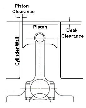
The piston is usually small in diameter than the bore of the cylinder. The space between the cylinder and the cylinder wall is called the piston clearance. This piston clearance provides a space for a layer of lubricant between the piston and cylinder wall to reduce friction.
- If the clearance is too small, there will be a loss of power from excessive friction, more wear, seizing of the piston in the cylinder.
- If the clearance is too much, the piston slap will result. Piston slap means sudden tilting of the cylinder as the piston moves down during the power stroke.
It prevents piston seizure due to high temperature. If there is on clearance then it is not possible to reciprocate piston inside the cylinder.
Functions of piston
- To transmit the power developed by fuel combustion to the crankshaft through the connecting rod.
- To form a seal so that high-pressure combustion gases do not escape to the crankcase.
- Piston serves as a support for the small end of the connecting rod.
- To suck the charge and push out the exhaust gases.
Constructional Features
- The top of the piston is called the head or crown.
- Towards the top of the piston, a few grooves are cut to house the piston rings. The bands left between the grooves are known as lands.
- The part of the piston below the ring is called Skirt is provided with bosses on the inside to support the piston pin (Gudgeon pin).
- The distance between the axis of the piston pin and the top of the piston crown is called compression height.
Type of pistons
- Cast Iron Pistons
- Forged pistons
- Cast Steel Piston
- BI-metal piston
- Two-piece piston
- Oil-cooled pistons
- Anodized piston
- Tinned pistons
Piston materials: Cast Iron, Aluminium, Lo-Ex Alloy, Invar, Steel alloy.
Protective coating: Cadmium plating, Anodised pistons, Tinned pistons, Chromium plating.
#9 Piston Rings
The piston rings are fitted into the grooves of the piston to maintain a good seal between the piston and the cylinder wall.
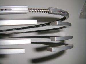
The number of piston rings used is about 2 to 4 compression rings and 1 to 2 oil control ring was used but in modern design the number if rings usually three out of which one is the oil control ring.
The function of piston rings
- To form a seal for the high pressures gases from the combustion chamber entering into the crankcase.
- The piston ring provides easy passage for heat flow from the piston crown to the cylinder walls.
- To maintain sufficient lubrication oil on cylinder walls throughout the entire length the piston travel, hence it minimizes the cylinder wear.
Construction
- The ring is generally cast individually and machined carefully so that when in the position it is able to exert uniform pressure against the cylinder walls.
- A gap has been cut at the end.
- In practice, the piston ring end gap when installed is kept about 0.30 to 0.35mm.
- The gap is almost closed when the piston is inside the cylinder, so that piston and cylinder.
- Butt type
- Taper type
- Lap type
Material for Piston Rings
- fine-grained alloy cast iron containing silicon and manganese. It has good heat and wears resisting qualities.
Chromium plated rings are also used for the top ring, which is subjected to the highest working temperatures and the corrosive action of the combustion products.
Types of Piston Rings
- Compression rings: Fig shown a simple sketch of Compression rings. these rings effectively seal the compression pressure and the leakage of the combustion gasses. these are fitted in the top grooves. They also transfer heat from the piston to the cylinder walls.
- Oil control rings: The Figure shows a simple sketch of oil control ring. The main purpose of the oil ring is to scrape the excess oil from the liner and return it back to the oil sump during the downward and upward movement of the piston. It prevents the oil from reaching the combustion chamber. One of two oil control rings is used in a piston. If two rings are used one has fitted above and other is fitted below the gudgeon pin in the piston These rings are provided with drain holes or slots. these slots allow the scraped oil to reach into the oil sump through the piston holes.
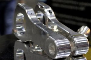
#10 Connecting Rod
Fig showed a connecting rod. It is fitted in between the piston and crankshaft.
The main function of the connecting rod is to convert the reciprocating motion of the piston into the rotary motion of the crankshaft.
It must be light and strong enough to withstand stress and twisting forces.
Construction
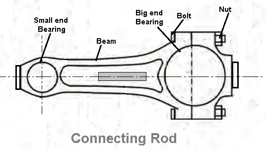
- The connecting rod usually has I-beam cross-section and is made of alloy steel of duralumin by drop forging.
- Nowadays it is also cast from malleable or spheroidal graphite C.I.
- The small end of the connecting rod has either a solid eye used to connect the piston by the piston pin.
- The big end of the connecting rod is always split is used to connect the crank pin of the crankshaft.
#11 Piston Pin
The piston pin is also called wrist pin or gudgeon pin. It is used for connecting the small end of the connecting rod and the piston.
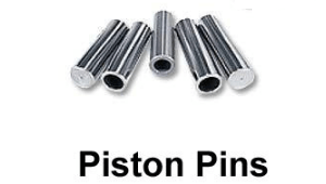
Construction: It is made hollow to reduce weight and it is made from case hardened steel.
- Set screw types piston pin.
- Semi-floating piston pin
- Fully floating piston pin
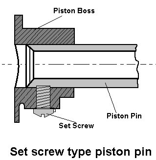
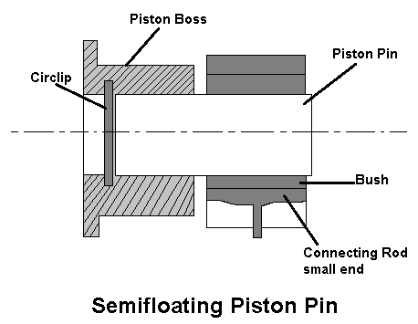
Fig (a) shown Set screw type piston pin, This pin is fastened to the piston to the piston by a SET SCREW such that the connecting rod end swivel has required by the combined reciprocating and rotary motion of the piston and crankshaft.
Fig (b) shown the Semi-floating piston pin, It is fastened to the connecting rod with a clamp screw.
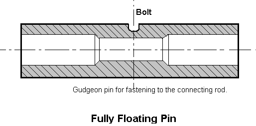
Fig (c) shown Fully floating piston pin. The pin floats in both the piston bosses and the small end of connecting rod. It is prevented from coming in contact with the cylinder wall by two circlips.
#12 Crankshafts
The crankshaft is the engine component from which the power is taken. It is one of the main power transmission sources in all engine parts.
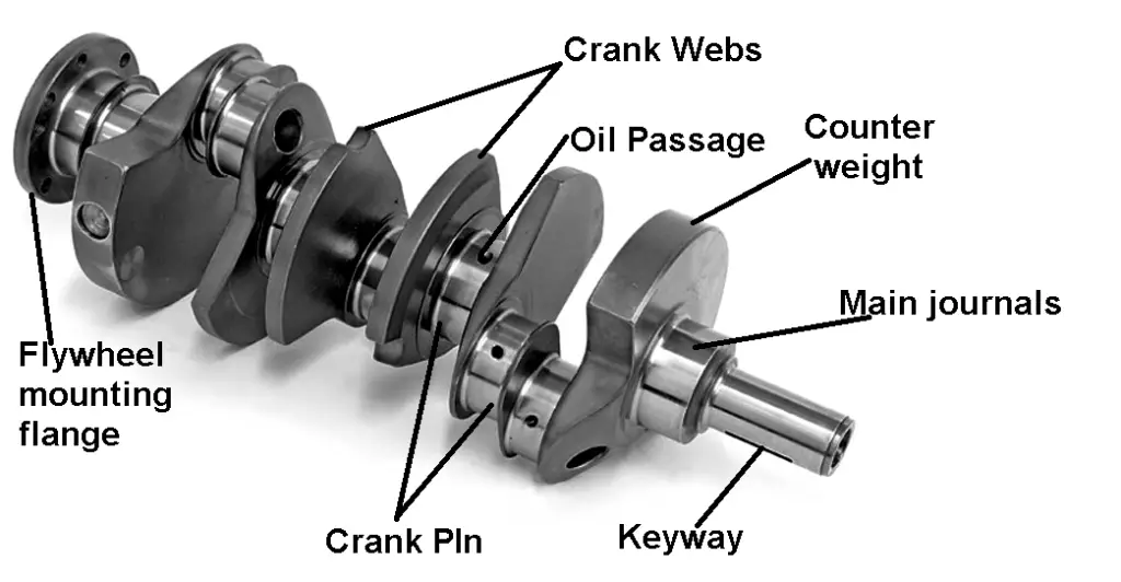
The Crankshaft is the first part of the power transmission system in which the reciprocating motion of the piston is converted into the rotating motion with the help of connecting rod.
Construction

- The crankshaft is made of casting or forging of heat treated alloy steel and is machined.
- A crankshaft consists of crankpins, weds, balancing weight and main journals and oil holes.
- The big end of the connecting rod is connected to the crankpin of the crankshaft.
- Centre to centre distance between the crankpin and crankshaft is half of the piston displacement during the stroke.
- Thus one complete revolution of the crankshaft makes two strokes of the piston.
- Balancing weights are provided on the opposite side wed for balancing. The crankshaft has drilled oil passages through which oil flow the main bearing to the connecting rod bearings.
- A gear that drives the camshaft,
- The vibration damper to control torsional vibration, and
- The fan belt pulley. This pulley drives the engine fan, water pump, and generator with a V-belt.
The rear end of the crankshaft carries flywheel. The flywheel tends to keep the crankshaft running at constant.
Next, to the rear end, the main journal and oil seal is fitted. In some engine, oil return threads are provided which return the lubricating oil to the sump.
- In one piece type, all the parts are integral and are formed by drop forging and then machining.
- In build-up type, the crankpins and journals are fastened to the crank webs.
#13 Camshaft
A camshaft is a shaft on which cams are mounted. A cam is a device that changes the rotary motion of the camshaft into the linear motion of the follower. A camshaft is responsible for the opening of the valves.
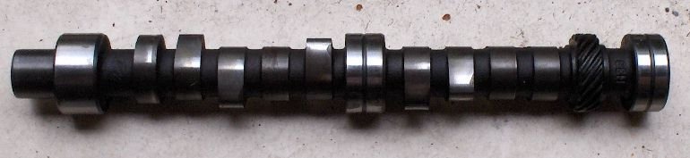
Construction
- A camshaft has a number of cams along the length, two cams for each cylinder, one to operate the inlet valve and the other the exhaust valve.
- In addition, the camshaft has an eccentric to operate the fuel pump and gear to drive the ignition distributor and oil pump.
- The camshaft is driven by the crankshaft. The camshaft gear has twice as many teeth as the gear on the crankshaft.
- Camshaft made from forged alloy steel.
This gives 1:2 gear ratio, the camshaft turns at half the speed of the crankshaft.
Working
- Thus, every two revolutions of the crankshaft produce one revolution o the camshaft and one opening and closing of each valve, in the four-cylinder engine.
- Thus there is correct opening and closing of the valves takes in relation to the position of the piston in the cylinder.
- Gear drive.
- Chain drive.
- Belt drive.
#14 Flywheel
The flywheel used in a transmission system of a vehicle. Using the principle of conservation of angular momentum, it stores rotational energy, which is a kind of kinetic energy proportional to the sum of its moment of inertia and the square of its rotational speed.
Torque is produced by the engine, but it varies and is not constant. It will not only make the rider incredibly uncomfortable, but it will also reduce the lifespan of its many parts. To solve the problem of fluctuating load, a flywheel is used.
Construction
- A flywheel is a heavy steel wheel attached to the rear end of the crankshaft.
- The size of the flywheel depends upon the number of cylinders and the construction of the engine.
Working
- During the power stroke, the engine tends to speed up and during the other strokes, it tends to slow down.
- The inertia of the flywheel tends to keep the running of the crankshaft at a constant speed. Hence the engine speed is maintained constant.
#15 Engine Valves
Engine valves are essential to control the timing of air-fuel mixture entry into the cylinder and combustion products out of the cylinders.
Construction
- These are located at the inlet and outlet opening of the engine cylinder.
- The valves fit on the valve seats in their closed position.
- Poppet valve
- Sleeve valve
- Rotary valve
15.1 Poppet valve
This is the most widely used valve in automobile engines. The poppet valve is given the name because of its motion of popping up and down.
Its construction is very simple. This is also called a mushroom valve, because of its shape.
Construction
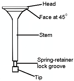
- It consists of a head and a stem. The valve face usually with an angle of 30° to 45° is ground perfectly, since it has to match with the valve seat for perfect sealing.
- The stem has a spring retainer lock groove and the stem end is in contact with cam for up and down movements of the valve.
15.2 Sleeve Valve

The sleeve valve as the name implies, that it is a tube or sleeve kept between the cylinder wall and the piston.
Construction
- The inner surface of the sleeve actually forms the inner cylinder barrel in which the piston slides.
The sleeve is in continuous motion and admits and drives out the gases by virtue of the periodic coincidence of port cut in the sleeve with ports formed through the main cylinder casting.
Advantages:
- Simple in construction.
- Sleeve valves are silent in operation.
- There is noise because there is no noise-making parts like valve cams, racker arm, tappets valves etc.,
- The tendency of detonation is less.
- Cooling is very effective as the valve is in contact with water jackets.
Disadvantages:
- High oil consumption for lubrication as a larger area of sleeve surface to be lubricated.
- Cleaning of the ports and the valve is complicated.
15.3 Rotary valve
Fig showed a simple sketch of Rotary Valve. There are many types of rotary valves. The figure shows the disc type rotary valve. It consists of a rotating disc which has a port. While rotating, it communicates s alternately with the inlet and exhaust manifolds.
Advantages:
- Rotary valves are simple in construction.
- These valves are manufactured at cheaper costs.
- They are suitable for high-speed engines.
- Stresses and vibrations are less compared to poppet and sleeve valves.
- They are smooth in operation and are uniform and noise-free operation.
Disadvantages:
- It is difficulties in pressure sealing between the rotary disc and cylinder.
- Efficient valve lubrication is difficult.
Materials for valves
The materials used for inlet and exhaust valves are generally different because of the different operating conditions to which valves are subjected.
Silico-chrome steel is the material generally used for inlet valves. For exhaust valves, molybdenum is added to the silico-chrome.
The recent materials for exhaust valve are austenite steel and precipitation hardening steel is generally used.
#16 Governor
In petrol engines, the carburetor control both air and fuel supply to the engine cylinder under speed and load conditions.
- The main functions of a governor are to regulate the supply of fuel through some mechanism so that the engine speed remains within its range.
Working:
- On increased load, the engine speed decreases.
- When the load decreases, the engine speed increases.
Without a governor, the engine speed increases at lighter loads and the dynamic stresses damage the engine parts.
The governor which is set for a particular engine speed operates a mechanism such that more fuel is injected to increase the engine power.
Governor, in this case, operates the mechanism to reduce the supply of fuel in the engine. It is essential to keep the engine speed within limits.
Types of Governor:
- Mechanical Governor or Torque control Governor or Centrifugal governor.
- Pneumatic Governor.
- Hydraulic Governor.
#17 Oil Filter
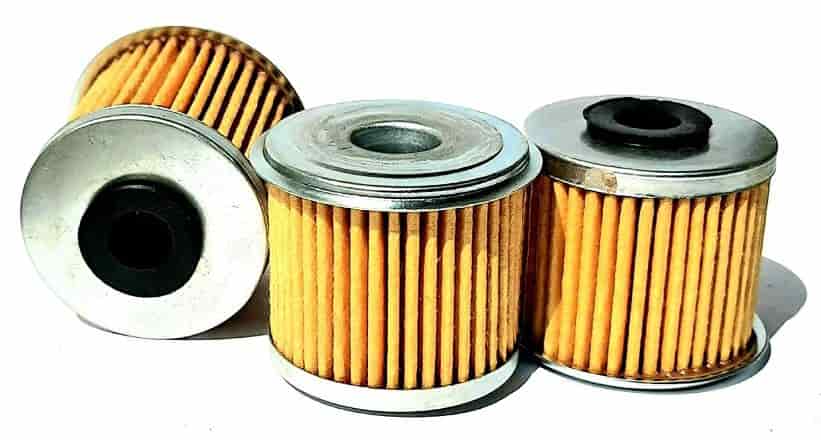
The oil filter aids in the removal of contaminants from your car engine’s oil that may build up over time as the oil keeps your engine clean. It filters the oil to remove harmful particles, metal shavings, and debris, allowing the engine to run smoothly.
Inadequate oil filtration could allow harmful contaminants to enter motor oil and damage your engine. If you filter out the trash, your engine oil will remain cleaner and last longer.
#18 Distributor
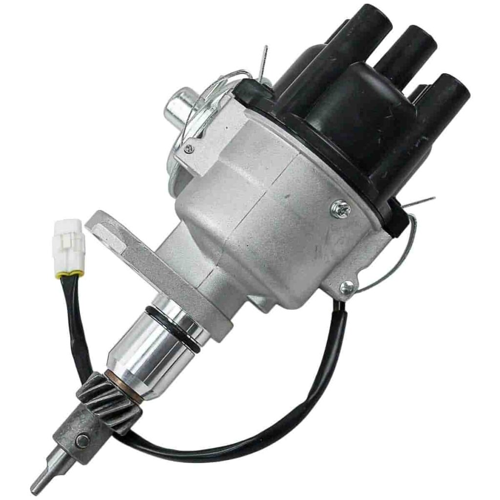
In old spark ignition engines, an electric and mechanical device called a distributor is used for ignition. It is the primary responsibility of the distributor to deliver secondary or high-voltage current to the spark plugs in the proper sequence and for the prescribed duration.
Except for magneto systems and many computer-controlled engines that use crank angle/position sensors, the distributor also has a mechanical or inductive breaker switch to open and close the coil’s primary circuit.
#19 Water Pump
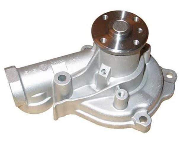
The water pump circulates coolant from the radiator to the coolant system, then into the engine, and back to the radiator. At the radiator, the heat that the coolant absorbed from the engine is transferred to the air. The coolant will not circulate in the system if there is no water pump, as it will simply sit there.
#20 Combustion Chamber
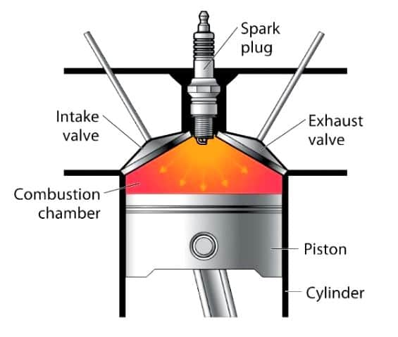
The area inside the cylinder where the fuel/air mixture ignites is a combustion chamber. The fuel/air mixture is compressed by the piston and ignited when it comes into contact with the spark plug, causing the mixture to burn, causing energy to be released from the combustion chamber.
The cylinder is where the Injector Nozzle, Piston, Spark Plug, Combustion Chamber, and other significant internal combustion engine components are kept.
#21 Timing Belt
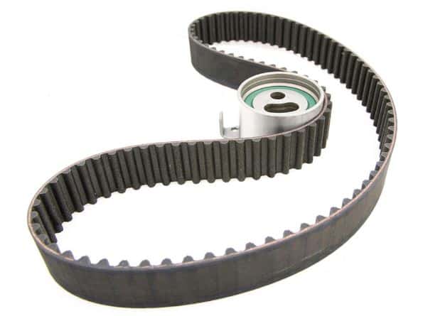
The engine’s camshafts are governed by the timing belt, which opens and closes valves at precisely the right times for smooth operation. The camshaft is turned in sync with the crankshaft by the teeth of the timing belt.
Additionally, an interference engine’s timing belt or chain prevents piston-valve contact. Typically, a timing belt is a drive belt with teeth on the interior surface. An example of a timing chain is a roller chain.
The camshaft and crankshaft pulleys are placed by gears on a rubber belt. The chain has teeth that let it wrap around pulleys like a bike chain. Certain vehicles, such as cars and trucks, employ more robust timing chains or gears.
#22 Rocker Arm
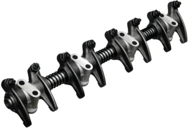
A rocker arm is a part of the valvetrain in an internal combustion engine that typically transmits the motion of a pushrod to the corresponding intake or exhaust valve.
Typically, stamped steel or aluminum is used to make rocker arms for cars, depending on the application’s need for higher revs. Some rocker arms have a bearing at the point of contact to lessen wear and friction.
Download PDF of this article
That’s it thank you for reading if you find this article helpful please share with your friends.
Subscribe to newsletter to get notification of our new posts:
- A Comprehensive Guide to Bike Engine Parts [Names & Functions]
- Working Principle of Single Cylinder Engine
- Understand The Difference Between Petrol and Diesel Engines
What are the main parts of a car engine?
Parts of a Car Engine
Cylinder Block, Cylinder Head, Crank Case, Oil Pan, Manifolds, Gasket, Cylinder Liner, Piston, A Piston Ring, Connecting Rod, Piston Pin, Crank Shaft, CamShaft, Flywheels and Engine Valves.
What is the application of a cylinder head in a car engine?
The cylinder head cast integrally with cylinder blocks also be done in a few cases usually in racing cars to obtain a gas-tight joint. Types of integral heads have advantages over integral construction. However, some heavy-duty engines require higher cooling rates such as copper alloys that can be used in racing cars.
What is the function of a Connecting Rod?
The main function of the connecting rod is to convert the reciprocating motion of the piston into the rotary motion of the crankshaft.
What is the function of piston rings in a car engine?
1. To form a seal for the high pressures gases from the combustion chamber entering into the crankcase.
2. The piston ring provides easy passage for heat flow from the piston crown to the cylinder walls.
